
Dialling down your Z-offset guarantees great bed adhesion, but it quietly ruins your functional prints before the second layer even starts. We've all pulled a multi-part mechanical project off the plate, tried to slide interlocking joints together, and watched them jam because of an uneven, flared base rim. Dialling in your setup shouldn't feel like pure guesswork, especially when over-correcting risks lifting prints mid-job. To solve this dimensional headache, mastering your elephant foot compensation slicer settings is the single fastest way to bring parts back into spec.
This guide shows you how to eliminate bottom-layer bulge and achieve crisp 90-degree base edges across Bambu Studio, UltiMaker Cura, and PrusaSlicer. You'll learn how to separate hardware adjustments from software fine-tuning, dial in repeatable first-layer precision across PLA, PETG, and ABS, and protect your bed adhesion throughout the process. Here is the reliable calibration routine you need to dial in your slicer profiles with complete confidence.
Key Takeaways
- Separate physical nozzle over-compression from heat-bed deformation by checking mechanical tramming and Z-offset before adjusting software.
- Dial in targeted elephant foot compensation slicer settings across Bambu Studio, PrusaSlicer, and UltiMaker Cura to retract initial layer perimeters cleanly.
- Use a stepped calibration test model and digital callipers to measure real-world dimensional flare and determine your exact compensation value.
- Integrate CAD-level base chamfers and choose high-stability filaments to protect tight tolerances on functional, interlocking assemblies.
What Is Elephant Foot and Why Does It Occur?
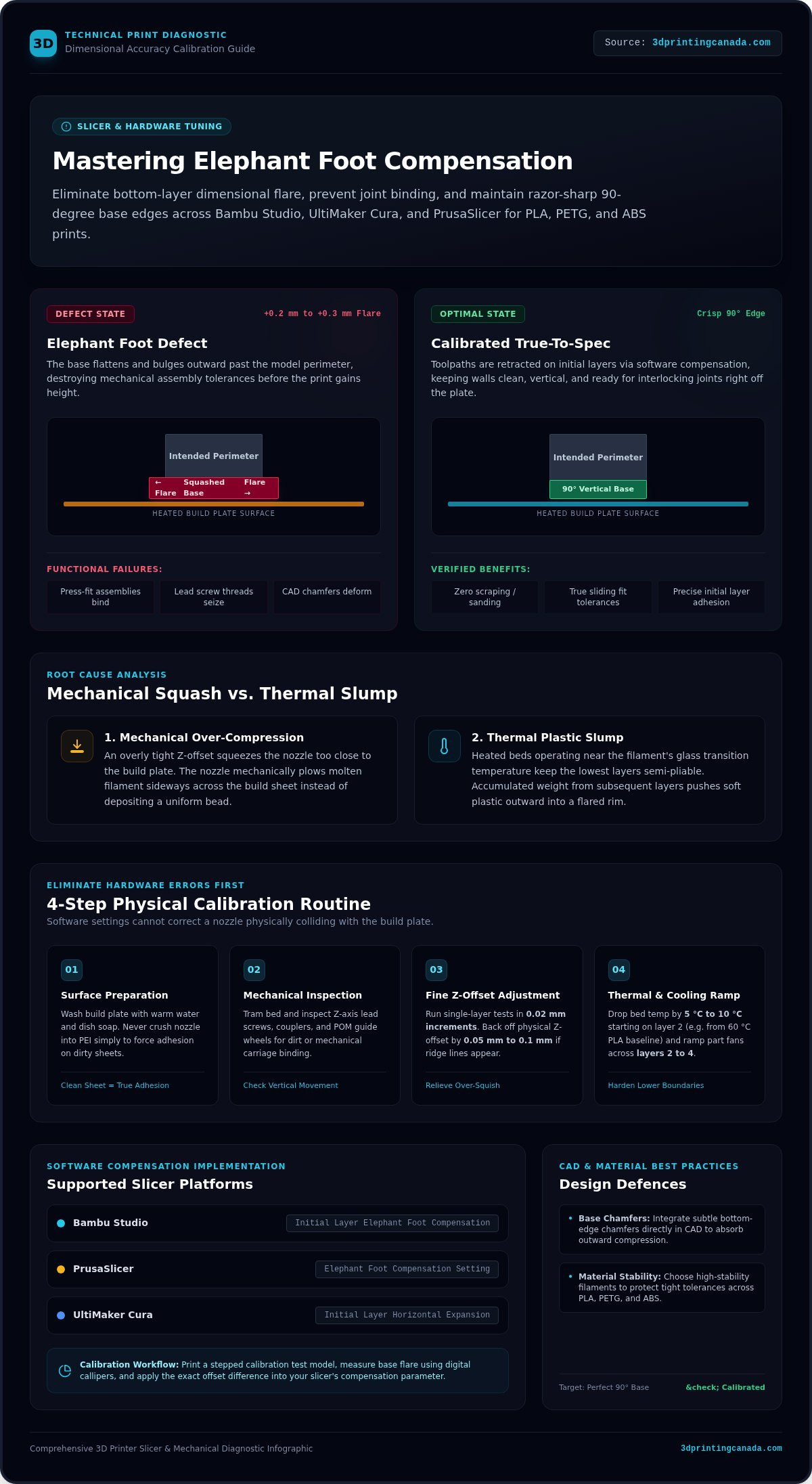
Elephant foot describes the outward dimensional bulging that develops along the bottom few millimetres of a 3D print. Instead of rising with crisp, perfectly vertical 90-degree walls, the base flattens and spills outward past the model's intended perimeter. In standard Fused Deposition Modeling (FDM) printing, this defect ruins dimensional tolerances before your print even gains height.
Most makers treat this issue as a pure slicing error, but resolving it requires separating physical machine calibration from software adjustments. While adjusting your elephant foot compensation slicer settings provides an effective software fix, ambient temperatures and build chamber dynamics also influence the outcome. When warm air pools around the base of the print without adequate cooling, initial layers stay molten longer, allowing the extruded material to settle outward under its own weight.
Mechanical Squash vs Thermal Slump
Two distinct forces drive bottom-layer flare: physical over-compression and thermal plastic slump. A mechanical squash occurs when an overly tight Z-offset squeezes the nozzle too close to the build plate. The nozzle mechanically forces molten filament sideways across the build surface rather than laying down a standard bead.
Thermal slump occurs right at the build plate interface. Heated print beds operate near the filament's glass transition temperature to ensure reliable adhesion. This constant heat keeps the lowest layers semi-pliable. As the print head deposits subsequent passes, the accumulated downward mass of dense infill and walls compresses that soft plastic beneath it, pushing it outward into a flared rim.
The Functional Impact on Dimensional Accuracy
A rim flare of just 0.2 mm or 0.3 mm might look like a minor cosmetic blemish, but it quickly ruins functional mechanical projects:
- Press-fit assemblies bind: Bearings, alignment pins, and sliding joints fail to seat cleanly into their mating recesses.
- Lead threads seize up: Screw threads printed near the base plate flatten out, causing cross-threading or total binding during initial assembly.
- Chamfers deform: Subtle design features like bottom edge bevels and fillets get squashed flat against the plate.
Relying on sandpaper or a deburring blade to carve off bottom rims adds tedious post-processing and compromises precision. Applying targeted elephant foot compensation slicer settings lets you eliminate this flare at the toolpath level while keeping your parts completely functional right off the plate.
Hardware and Bed Calibration Checks Before Changing Slicer Settings
Software adjustments cannot fix a nozzle that physically plows into the print bed. Before tweaking software parameters, eliminate mechanical errors on the machine itself. Reviewing the common causes of elephant's foot reveals that physical over-compression and improper bed temperatures account for most base flaring. Start by tramming your bed manually or running a fresh automated mesh. Inspect your Z-axis lead screws, couplers, and POM guide wheels for dirt or mechanical binding. If the carriage binds during its first few vertical steps, the nozzle stays trapped too close to the surface, squashing the lower layers flat.
Dialling In the Optimal First-Layer Z-Height
Many makers crush their nozzle into the bed plate simply to force bed adhesion on a dusty or oily sheet. Wash your build plate with warm water and basic dish soap instead of burying your nozzle into the PEI. A clean surface provides grip without excessive downward force.
Run a single-layer test print and adjust your live Z-offset in small 0.02 mm increments. You want adjacent extrusion lines to melt together into a continuous, smooth sheet. If you feel raised ridges between toolpaths, your nozzle is too close. Backing off your physical Z-offset by just 0.05 mm to 0.1 mm relieves excess squish immediately and removes the bulk of your outward flaring.
Managing Heated Bed Temperatures and Thermal Creep
Filament requires warmth to adhere, but excessive heat keeps bottom perimeters soft long after extrusion. For standard PLA, running a print bed at 60 °C keeps the base polymer right at its glass transition threshold. The weight of subsequent passes quickly forces that malleable foundation outward.
Lower your build plate temperature by 5 to 10 °C starting on layer two. This drop hardens the perimeter boundaries while preserving steady plate adhesion. Configure your slicer cooling settings so part fans ramp up progressively across layers two through four. If hardware adjustments and thermal tuning still leave a stubborn edge rim, bringing your printer to a stable baseline makes adjusting your 3D printer repair services or tuning your elephant foot compensation slicer settings predictable and effective.
Elephant Foot Compensation Slicer Settings Across Major Platforms
Modern slicing engines handle bottom-layer dimensional correction by modifying the first-layer toolpath perimeter. Instead of scaling your entire 3D model, the software calculates an internal offset for the boundary walls resting directly on the print bed. Understanding how to configure your elephant foot compensation slicer settings across different engines ensures that outer boundaries retract inward while interior infill density and upper layers remain untouched. Reviewing specific slicer-level solutions reveals clear differences in how these platforms label and calculate these values.
PrusaSlicer and SuperSlicer Configuration
In PrusaSlicer (including the preview builds of PrusaSlicer 3.0) and SuperSlicer, switch your interface to Advanced or Expert mode to expose the setting. Navigate to Print Settings > Advanced > Slicing and locate Elephant foot compensation.
PrusaSlicer uses positive millimeter values to contract the layer. Entering 0.2 mm tells the engine to offset the outer perimeter inward by that distance on the first layer. The software automatically detects thin internal features to prevent over-shrinking fragile geometry.
OrcaSlicer and Bambu Studio Setup
In Bambu Studio (such as version 2.8.3) and OrcaSlicer, open the Process panel and select the Quality tab. Scroll down to the Precision submenu to find Elephant foot compensation.
Bambu Studio defaults to 0.15 mm on most standard 0.4 mm nozzle profiles. When you inspect the slice preview, you might notice a small visual gap between the model base and an attached brim. Don't worry about this gap. The physical lateral squish of the molten plastic fills that space completely during real-world deposition.
UltiMaker Cura: Initial Layer Horizontal Expansion
UltiMaker Cura (up through stable version 5.13.0) handles this adjustment under the Walls (or Shell) settings category using a different naming convention: Initial Layer Horizontal Expansion.
Unlike PrusaSlicer and Bambu Studio, Cura requires a negative value to shrink the base layer. Enter -0.15 mm or -0.2 mm to pull the bottom perimeter inward:
- Initial Layer Horizontal Expansion: Applies strictly to layer one, offsetting only the base rim.
- Horizontal Expansion: Applies across all layers, changing the outer dimensions of your entire model.
Entering a positive number here will expand the base further, making your bottom flare worse. Matching the correct sign convention to your slicer keeps your compensation precise.
Step-by-Step Calibration Routine to Dial In Your Exact Values
Dialling in your slicer without measurements turns calibration into an endless cycle of trial and error. You cannot correct a mechanical flare by eyeball. Establishing a reliable, data-driven routine gives you exact compensation numbers tailored to your machine, build surface, and material profile.
Printing and Measuring Calibration Test Geometry
Slice a standard 20 mm stepped calibration cylinder or dimensional cube. Disable existing first-layer compensations and use your standard production speeds and layer heights (typically 0.2 mm). Let the print finish, then allow the build sheet to cool down to room temperature before detaching the part. Peeling hot plastic off the bed distorts the base and ruins your data.
Zero your digital vernier callipers and take three precise readings across the X and Y axes:
- First layer: Measure across the very bottom edge where flare occurs.
- Second layer: Measure just above the initial layer seam line.
- Upper body: Measure across the midpoint (around layer twenty) to capture nominal dimensions.
Calculating and Refining Compensation Values
Calculate your required correction mathematically. Subtract your nominal upper body width from your flared first-layer measurement. If your nominal dimension reads 20.00 mm and the first layer measures 20.36 mm, your total dimensional error is 0.36 mm across the part.
Divide that error by two because the flare extends equally on both opposing perimeters. In this example, your single-wall offset is 0.18 mm. Enter 0.18 mm in Bambu Studio or PrusaSlicer, or -0.18 mm in UltiMaker Cura. Print a second validation cube. Refine the parameter in 0.02 mm increments until your bottom layer matches the rest of the body.
Troubleshooting Secondary Compensation Artifacts
Pushing compensation too far creates new problems. If you retract the perimeter too aggressively, first-layer corner contact shrinks, causing parts to detach mid-print. On parts with internal mounting holes, verify that your hole diameters remain true and don't bind against shafts.
If you notice inner walls separating from outer perimeters on the bottom face, bump your first-layer line width up by 5% to 10% to ensure solid mechanical bonding. For persistent dimensional issues or worn motion components, work with our bench technicians to access dedicated 3D printer repair services and bring your motion system back to peak factory alignment.
Advanced Techniques: Design-Level Fixes and Hardware Maintenance
Dialling in your toolpaths solves most bottom-layer spread, but mechanical designs sometimes demand extra clearance. When high-load mechanical parts or structural brackets face extreme build plate heat, combining slicing adjustments with smart CAD modelling creates an infallible baseline. Choosing high-stability, precision-tolerance filaments engineered with lower thermal creep also helps perimeters solidify cleanly right at the build plate surface.
CAD Chamfers and Fillets on Model Base Edges
If you design your own functional 3D models, build a permanent mechanical buffer right into your geometry. Add a subtle 45-degree chamfer between 0.5 mm and 1.0 mm to every bottom edge resting against the build plate.
This negative angle acts as an expansion reservoir. When the nozzle lays down molten plastic and downward pressure pushes the bead sideways, the excess material flows upward into the empty chamfer relief instead of spilling outward past your model's true boundary. Pairing a modest CAD chamfer with balanced elephant foot compensation slicer settings eliminates base flare completely without compromising plate contact area.
Hardware Upgrades and Expert Diagnostic Support
Software offsets cannot compensate indefinitely for worn mechanical assemblies. Build a habit of cleaning your Z-axis lead screws, lubricating linear rails, and inspecting anti-backlash nuts for backlash or grime. If your gantry tilts or your lead screw binds during its first half-millimetre of travel, the nozzle will squash consecutive initial layers together regardless of your profile adjustments.
Inspect your build sheets for uneven wear, residual adhesive buildup, or heat spots. Refreshing your machine with high-grade magnetic sheets or genuine Bambu Lab accessories restores the planar flatness needed for repeatable first-layer adhesion. Modern high-acceleration machines also introduce distinct thermal demands. You can track how new heating and motion systems influence print dynamics in our breakdown of fast 3D printer trends.
When stubborn base distortion persists across multiple filaments despite fine-tuning your elephant foot compensation slicer settings and bed temperatures, physical machine misalignment is usually the culprit. In those cases, working with professional bench technicians through dedicated 3D printer repair services quickly pinpoints worn lead screws, bent gantries, or bed-sensor drift to restore crisp, square parts to your build plate.
Achieve Flawless First-Layer Precision on Every Print
Flared base edges don't have to compromise your functional builds. Dialling in your physical Z-offset and lowering bed heat establishes a reliable baseline, while fine-tuning your elephant foot compensation slicer settings delivers the micron-level precision needed for clean, press-fit assemblies. Pair those toolpath adjustments with methodical calliper measurements, and you'll eliminate base rim binding permanently.
When software compensation meets physical limits, having dependable hardware makes all the difference. As a trusted nationwide Canadian supplier of additive manufacturing hardware, 3D Printing Canada supports your workshop with factory-calibrated components, high-grade filaments, and experienced bench technicians ready to troubleshoot stubborn mechanical issues. Explore our premium 3D printing supplies and accessories across Canada to upgrade your setup. With a calibrated profile and a well-maintained motion system, your next mechanical build will snap together effortlessly straight off the build plate.
Frequently Asked Questions
What is the default value for elephant foot compensation in modern slicers?
Most modern slicers set a baseline between 0.1 mm and 0.2 mm, or leave the feature disabled until you configure it. Bambu Studio commonly defaults to 0.15 mm on standard 0.4 mm nozzle profiles, while PrusaSlicer sets its initial baseline around 0.2 mm. UltiMaker Cura leaves the setting at 0.0 mm out of the box. Dialling in your specific elephant foot compensation slicer settings requires checking these defaults against test measurements.
How does elephant foot compensation differ from initial layer horizontal expansion?
Both parameters achieve the exact same mechanical outcome, but they use opposite numerical conventions depending on the software engine. PrusaSlicer and Bambu Studio call the parameter elephant foot compensation and use positive millimetre values to retract outer paths. UltiMaker Cura labels it initial layer horizontal expansion and requires a negative value, such as -0.2 mm, to shrink the first layer perimeter. Entering a positive value in Cura actually makes the flare worse.
Can improper bed levelling cause elephant foot even with correct slicer settings?
Yes, mechanical bed tilt or an overly tight Z-offset easily overwhelms software adjustments. If the nozzle rides too close to the textured sheet during the first layer, it physically squashes molten plastic outward across the plate. Software offsets only pull perimeter toolpaths inward by a fixed distance. They cannot stop extra material from mushrooming sideways when the physical vertical gap is simply too small to accept the extruded filament volume.
Does elephant foot compensation affect raft or brim dimensions during slicing?
Slicers generally apply compensation to the model boundary rather than altering the outer brim contours. When you enable the setting, you might notice a thin visual separation between the model edge and the inner brim line in your preview screen. This small gap is intentional. Molten filament squish fills that space during extrusion, preserving steady plate adhesion while keeping your part perimeters true to their nominal CAD dimensions.
Can high bed temperatures cause elephant foot on PLA prints?
Yes, keeping a heated bed near 60 °C keeps standard PLA close to its glass transition point throughout the entire build. When the polymer remains warm and soft, the downward weight of infill and upper layers compresses the base, causing thermal slump. Dropping your bed temperature by 5 to 10 °C after the initial layer allows outer perimeters to cool, freeze their dimensions, and resist mechanical sagging.
Why does elephant foot ruin functional press-fit and screw-together 3D models?
A flare of just 0.15 mm adds roughly 0.3 mm of total width across outer diameters, destroying tight engineering tolerances. For press-fit bearings or locating pins, that flared collar prevents parts from sliding into matching sockets without aggressive filing. On threaded assemblies, elephant foot distorts lead-in threads right at the base, resulting in cross-threading, galling, or complete mechanical binding during assembly. Calibrated elephant foot compensation slicer settings keep these bottom edges flush.
Is elephant foot compensation necessary when printing with a raft?
No, elephant foot compensation is completely unnecessary when using a raft. A raft absorbs both nozzle squish and thermal slump across its sacrificial base layers. The actual model begins several layers above the heated plate, supported by an air gap that allows normal perimeter geometry without flare. Slicers automatically bypass first-layer compensation settings on the model when generating a raft underneath your part.