
A secure, reusable screw connection can depend on a well-matched hole and a steady hand. A hole that’s too tight, too shallow, or poorly aligned may split or deform the print before the insert is seated. This threaded brass heat-set inserts installation guide covers the practical details that help make the process predictable.
If you’re unsure which insert size to choose or how much heat to apply, start by checking the insert’s dimensions and the printed feature. The hole, surrounding wall thickness, filament, and installation tool all affect the result. A reliable installation starts with matching the geometry, then controlling heat and keeping the insert aligned as it settles.
Use the steps below to select an insert, plan its hole, prepare a thermoplastic part, and install the insert without forcing it. You’ll also learn how to inspect the finished connection and recognize common problems, including plastic pushed out around the opening and loose or tilted threads. These checks help you build stronger, reusable screw connections into functional 3D-printed parts.
Key Takeaways
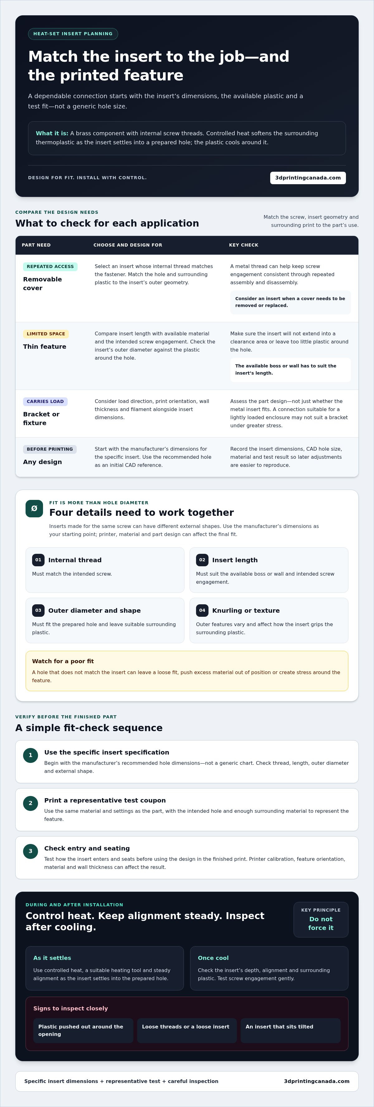
- Match the insert’s thread, length, outer diameter, and knurling to the part’s job and the manufacturer’s dimensions.
- Plan the printed hole and surrounding walls for the insert, then test the design with the filament you’ll use.
- Follow a controlled installation process with steady alignment and a suitable heating tool.
- Compare heat-set inserts with captured nuts, thread-forming screws, and printed threads to choose a fastening method for your application.
- After cooling, check the insert’s depth, alignment, and surrounding plastic, then test screw engagement gently.
What threaded brass heat-set inserts add to a 3D-printed part
A threaded brass heat-set insert is a metal component with internal screw threads, installed into a prepared feature in a thermoplastic part using controlled heat. Heat softens the surrounding plastic as the insert settles into the hole. When the material cools, the insert provides a metal thread for a fastener.
A metal thread is useful when a screw needs to come out and go back in without repeatedly cutting into the printed plastic. Driving a screw directly into plastic can wear the hole during repeated assembly and disassembly. An insert provides a defined threaded surface, helping keep screw engagement more consistent during service or adjustments.
For example, an electronics enclosure cover that needs to be removed for maintenance may benefit from inserts. They can also suit brackets, fixtures, and functional assemblies that need to be fastened together. Inserts aren’t necessary for every print: if a joint will be assembled once and left alone, a simpler fastening method may be adequate. Choose based on how the part will be used, not simply because a metal thread is possible.
When a heat-set insert is useful
Consider an insert when a joint needs repeated fastening, a cover needs to be replaceable, or a screw must engage at a consistent position. Before designing around one, consider the forces the part will carry. Print orientation, wall thickness around the insert, and filament choice all affect how those forces travel through the plastic. A connection that works in a lightly loaded enclosure may not suit a bracket under greater stress.
How the insert bonds with printed plastic
A heated insert softens the thermoplastic around its prepared hole as it is pressed into place. The plastic then cools around the insert. Many inserts have knurled or otherwise textured outer surfaces that help resist rotation or pull-out when properly embedded. The result depends on both the insert geometry and the printed hole. A poor fit can leave too little plastic to grip or push excess material out of position.
Fit depends on more than the hole diameter. The insert’s outer shape, length, and knurl pattern affect how it sits and how the plastic flows around it. A hole that doesn’t match the insert may leave a loose fit, a raised rim, or stress in the surrounding feature. Use the insert manufacturer’s dimensions as your starting point, then account for your printer, material, and part design. Don’t assume one hole size will work for every combination.
A successful threaded brass heat-set inserts installation guide starts with the job the joint needs to do. Plan for the screw, the forces on the assembly, and the space around the insert. For a functional part, leave enough material around the feature and orient the print with the connection in mind. These design choices help set up a clean installation and a dependable screw connection.
Choose the right brass insert, printed hole, and installation approach
Start with the insert manufacturer’s dimensions, not just a familiar screw size or a hole chart found online. The insert’s thread size identifies the screw that fits inside it. Its outer diameter and length determine how it fits into the printed part. Inserts designed for the same screw can have different external shapes, so don’t assume they use the same hole.
Rule of thumb: match the hole to the specific insert specification, not a generic chart. Published hole dimensions are a starting point, not a guarantee of fit on your printer. Printer calibration, material, and the orientation of the feature can affect the final result. Test the design before printing the finished part.
Match insert geometry to the part
Choose an insert length that provides suitable screw engagement while fitting within the available boss or wall. Check the outer diameter against the material around the hole as well. Knurl patterns and other exterior features vary, and different designs grip the surrounding plastic in different ways. Confirm the insert’s internal thread matches the intended screw before designing the mating component.
Use this planning framework to connect the part’s needs with the design checks:
- Repeated access, such as a removable cover: Select an insert with a thread that matches the fastener. Check that the hole and surrounding plastic suit its outer geometry.
- A thin feature or restricted space: Compare the insert length with the available material and intended screw engagement. Make sure the insert won’t extend into a clearance area or leave too little plastic around the hole.
- A load-bearing bracket or fixture: Consider load direction, print orientation, wall thickness, and filament alongside the insert’s dimensions. Check the part design, not just the fit of the metal component.
- Any design before printing: Record the manufacturer’s insert dimensions, the CAD hole size, the material, and the test result. A simple record makes later adjustments easier to reproduce.
Design and print a suitable installation hole
Use the insert manufacturer’s recommended hole dimensions as your initial CAD reference. Then print a small test coupon with the same material and settings as the part. Check how the insert enters and seats before using the design in a finished print. Printer calibration and layer direction can affect the hole’s shape, while the material and surrounding wall thickness influence how the feature responds during installation.
Include the intended hole and enough surrounding material in the test coupon to represent the actual part. If the insert won’t seat as expected, adjust the design in small, controlled steps and print another coupon rather than forcing it into the final piece. Testing is especially useful when you change filament or insert geometry. Plan the material around the finished joint, and explore 3D printing materials and resources as part of that process.
Heat-set inserts versus other threaded fastening options
A brass insert is one way to add a reusable screw thread to a print, but it isn’t the right answer for every joint. Compare fastening methods based on how often you’ll assemble the part, whether you can reach the back of the joint, the part’s shape, and the loads it must handle. A removable enclosure cover has different needs from a prototype bracket that will be assembled once.
Heat-set inserts can damage a print if heat, alignment, or fit isn’t controlled. Excess heat can deform nearby plastic, while an unsuitable hole or insertion path can stress the feature. Choose a method that fits the design, then follow the fastener and material guidance for that approach.
When to use inserts instead of printed threads
For a joint that will be opened repeatedly, a metal thread can provide more consistent screw engagement than a thread formed directly in plastic. Printed threads may still work well for prototypes, low-use parts, or designs with suitable geometry. Compare the screw size and material, and consider whether the layer orientation leaves the threaded feature vulnerable to splitting under the intended load.
When captured nuts or thread-forming screws may fit better
A captured nut can provide a metal thread without heat, but the design must hold the nut in place and allow it to be positioned during assembly. That may require access to the back or an opening in the enclosure. A thread-forming screw can suit some plastic joints when its design and installation follow the fastener maker’s guidance.
Use this decision guide to narrow the options:
- Heat-set insert: Consider it for repeated assembly when you can prepare a suitable hole and install the insert with controlled heat. It requires a compatible thermoplastic feature and careful alignment during installation.
- Captured nut: Consider it when the design can trap a nut securely and provide access to place it. The nut pocket takes space, and assembly may be awkward if the fastener side is enclosed.
- Thread-forming screw: Consider it for a suitable plastic joint where the fastener can form its own thread. Follow the screw maker’s guidance, and account for the possibility that repeated removal may affect the plastic thread.
- Printed thread: Consider it for prototypes or low-use connections where the geometry and print quality support the thread. Small or fine threads can be more sensitive to printer resolution and material behaviour.
There’s no universal performance ranking. A connection’s result depends on the part, material, geometry, and assembly conditions. For a functional design, weigh those factors before settling on a method. This threaded brass heat-set inserts installation guide focuses on inserts, but the same design-first approach helps you select a fastening option that suits the job.
Install a threaded brass heat-set insert in a 3D print step by step
A clean installation depends more on preparation than force. Before starting, check that the insert, printed hole, filament, and heating tool are compatible. Follow the insert and tool manufacturers’ instructions for temperature and use. Don’t rely on a generic temperature setting: the appropriate heat depends on the materials and equipment involved.
Gather the essentials:
- A compatible threaded brass insert and a printed part with the prepared hole
- A controlled-heating tool with a suitable tip
- A stable, heat-resistant work surface and eye protection
Prepare the part and tool
Print a test coupon using the same material, settings, and hole design as the final part. Inspect the opening and practise on the coupon first. Secure the part so it can’t shift, with the insert opening easy to reach. Choose a tip that contacts the insert appropriately without pressing on or crushing nearby printed features.
Work through the installation in order:
- 1. Check the hole. Confirm it’s clear, undamaged, and designed for the specific insert. Don’t start if the opening is visibly misshapen or the surrounding feature is cracked.
- 2. Set up safely. Place the part on a stable surface and arrange the tool so you can approach the hole from above without twisting your wrist or moving the print.
- 3. Fit the insert to the tip. Seat the insert securely on the tool as directed by its manufacturer. Make sure it’s straight before bringing it towards the part.
- 4. Apply controlled heat. Follow the tool and insert instructions for the material and operating temperature. Let the insert warm gradually; don’t force a cold insert into the plastic.
- 5. Guide it into place. Bring the insert to the opening and apply steady, gentle pressure. Keep it aligned with the hole and the part’s face, stopping at the designed depth.
- 6. Remove the tool and let the part cool. Withdraw the tool carefully without tilting the insert. Leave the part undisturbed until the surrounding plastic has cooled.
Heat, place, and let the insert cool
Use the test coupon to learn how the plastic responds before working on the finished part. If the insert resists moving, stop rather than pushing harder. Forcing it can shift the print or damage the hole. Keep the tip and insert steady, and allow the material to flow around the insert instead of trying to drive it down quickly.
Straight, gradual placement helps preserve alignment and the surrounding plastic. After cooling, inspect the insert’s depth and position before testing screw engagement. For general 3D printing supplies and resources that support functional part design, explore 3D printing supplies.
Check the finished insert and fix common installation problems
Let the part cool completely before checking the insert. Look across the opening and from the side. The insert should sit at the designed depth, line up with the hole, and have no visible cracks in the surrounding plastic. If it’s meant to sit flush, check that it isn’t raised above the surface. If the design calls for a different depth, use that as your reference.
Test the thread gently with the intended screw. It should start without being forced and turn smoothly. Don’t use the screw as a lever to straighten a tilted insert. That can damage the internal thread or put extra stress on the plastic. Inspecting the insert now can catch problems before assembly.
Diagnose loose, tilted, or protruding inserts
Use the symptom as a clue, not as a reason to apply more force. A wobbly insert may indicate a hole that’s too large, too little surrounding plastic, or insert geometry that doesn’t suit the feature. A tilted insert can result from uneven tool contact or a part that shifted during placement. A protruding insert may have stopped short of its intended depth.
- Loose or wobbly: Recheck the hole dimensions, insert geometry, and material supporting the feature.
- Tilted: Review how the insert and tool met the opening, and whether the part was held securely.
- Protruding: Compare its position with the intended depth. Don’t push it farther once the surrounding plastic has cooled.
- Melted edges or a raised rim: Consider whether heat or pressure affected too much of the surrounding plastic, or whether the hole design needs adjustment.
- Insert rotates: Check the fit and surrounding support. Don’t rely on tightening the screw to hold the insert in place.
Before changing the process, try the adjustment on a test coupon made with the same material and hole design. Change one factor at a time, such as the hole fit, part support, or tool alignment, so you can identify what improves the result. Keep the manufacturer’s recommendations as your reference rather than making a large, untested change to the finished component.
Prevent damage and decide whether to rework
Stop if the part softens excessively, cracks, or deforms beyond the intended installation area. Reheating or removing an insert can disturb more plastic, so assess the feature and the part’s purpose before attempting rework. If repeated coupon tests still produce poor alignment or retention, revise the hole or surrounding geometry before printing another finished part.
A reliable threaded brass heat-set inserts installation guide doesn’t end when the insert is seated. Make inspection part of the build process, especially for parts that need regular service access. Choose materials and plan the part around the connection before printing.
Build your next functional part with confidence
Use each insert installation to refine your design. Record the insert and material, note how the test fit behaved, and carry successful results forward when you print a similar part. That simple habit can make future builds more consistent and help you catch fit issues before they affect an important component.
Keep this threaded brass heat-set inserts installation guide handy as you move from prototypes to functional prints. 3D Printing Canada supports makers and professional users with 3D printing equipment, materials, and technical services. Explore 3D printing equipment and supplies for your next project.
Frequently Asked Questions
Can you install a heat-set insert in a part that has already been printed?
Yes, you can install an insert in a printed thermoplastic part if the hole and surrounding feature were designed for it and you can reach the opening with the tool. Check that there’s enough material around the hole and that you can hold the part steady. A test coupon can help confirm the fit before you modify a finished component. The steps in this threaded brass heat-set inserts installation guide also apply to retrofits.
Can threaded brass heat-set inserts be used in resin 3D prints?
Generally, no. Heat-set inserts rely on thermoplastic softening around the metal and cooling to hold it in place. Many SLA and DLP printing resins are thermosetting materials, so they won’t soften and re-form in the same way. Heat may instead cause damage. For a resin part, consider a fastening method designed for its material, such as a captured nut planned into the geometry, and follow the resin manufacturer’s guidance.
Can you install heat-set inserts with a regular soldering iron?
Yes, a regular soldering iron can be used if you can control its heat and guide the insert without pushing on the printed part. A tip designed to contact the insert can make alignment easier, but the correct fit and operating temperature depend on the insert, tool, and filament. Follow their manufacturers’ instructions, and practise on a matching test coupon before installing an insert in a finished part.
Can a heat-set insert be removed and installed again?
You can sometimes remove an insert by reheating it carefully, but removal may soften or distort the surrounding plastic and weaken its grip. The brass insert itself may remain usable if it’s undamaged, but don’t assume the original hole will retain it securely after removal. Inspect the insert and part, then test the fit in a coupon or a non-critical feature before relying on the connection again.
What should you do if the screw is longer than the heat-set insert?
Check the screw’s usable engagement depth and the space behind the insert before assembly. A screw that extends beyond the insert may bottom out in a blind hole, protrude through the part, or interfere with another component. Choose a shorter screw or adjust the design to provide safe clearance. Don’t tighten a screw that has bottomed out, since it can stress the insert or damage the printed feature.
Do heat-set inserts make every 3D-printed part stronger?
No. An insert provides a metal thread, but it doesn’t automatically strengthen the surrounding print or suit every load. A thin wall, poor layer orientation, unsuitable material, or insufficient support around the insert can still cause the feature to crack or pull out. Match the fastening method to the part’s job, and assess the full joint, including the printed geometry and screw, rather than judging strength by the insert alone.